General Questions
Why does my device not react after connecting it to an AC power supply?
Ensure the correct connection of neutral conductor and phase. Both must not be interchanged on the whole line. Otherwise, the devices can be destroyed.
The analogue outputs of the devices generate their voltage signal against GND (ground). If there are different ground potentials between the devices, a short-circuit will occur at the PLC (or similar). The devices can be destroyed or have malfunctions.
If there is a common BUS line, a different ground potential will also cause a damage to the device.

When has my device been produced?
You will find a label on every device from Thermokon. It looks as follows:


The number in the upper right corner indicates the production date. The first two digits stand for the production year and the last three for the production day.
Example:
17 230 – year 2017
17 230 – day 230 in 2017
Why does my brightness sensor on the table shows other values than the brightness sensor in the ceiling?
The comparison of these two values naturally leads to a difference. However this is caused by the measurement setup and not by the used products.
The luxmeter on the table has its measurement element oriented to the ceiling. Usually that’s the direction of the illumination and the windows (light sources). Whereas the measurement port of the ceiling sensor is oriented to the ground. Therefore the ceiling sensor primarily measures the indirect light reflections of the surface below.

So the measurement value of the ceiling sensor will be lower than the luxmeter's. Between both values exists a constant difference factor. Via this difference factor the illumination at the table can be calculated out of the ceilling sensor's value.
Therefore a reference measurement must be performed once to determine this difference factor.
Why is there a deviation (unreasonable temperature measurement) with my passive temperature sensor?
Passive temperature sensors do not provide a voltage or current output. They change the resistance of the measuring element depending on the ambient (measured) temperature (e.g. PT1000, Ni1000).
This resistance value is transmitted to the controller (DDC, PLC, etc.) by wires and gets interpreted from it.
The resistance value does not only consist of the measuring element’s value. The line resistance and the contact resistance of terminal units are also part of the received signal (resistance) and end up in a slight deviation from the actual resistance of the (measured) temperature.

The wire resistance depends on the used wire type, the wire length, the conductor cross-section and the installation type. Based on these external factors, it may have a significant influence on the transmitted resistance value and may cause a significant deviation on the measured temperature.
Why the SAB05/SAB+ can't be mounted on a valve?
For mounting an SAB acutator on a valve, the drive spindle of the actuator has to be retracted completely.
If this is not the case, please proceed as follows:
SAB05
Open the case cover, remove the batteries wait 10 seconds and reinsert them.
The SAB05 drives into mouting position (drive spindle completely retracted) and can now be mounted on a valve. When successful, it is ready for normal operation again.

SAB+
Press the learn button on the back of the device for about 5 seconds.

The SAB+ drives into mounting position. The drive spindle is retracted completely and the radio communication is switched off.
After the SAB+ has been mounted on the valve, press the learn button again for about 1 second. Now the SAB+ is ready for normal operation again.
How to prevent theft and vandalism of SAB actuators?
Unfortunately, the theft of or vandalism at SAB actuators occurs. To avoid this, the following measures can be taken:
SAB05
Battery protection: The battery protection SAB05 (item no. 595612) prevents theft of batteries.
The battery compartment can be locked by a special screw requiring a tool.
SAB05 and SAB+
The saftey lock dismounting protection SAB (item no. 706148) prevents the tooless disassembley of an SAB actuator from a valve.
This protection covers the securing nut of the SAB actuator.
Why does the LRWapp/NOVOSapp/USEapp not establish a connection to the Bluetooth dongle?
If it is not possible to establish a connection via the USB Bluetooth dongle, please proceed as follows:
- Reinstall the app
- Restart your smartphone or tablet
- Reconnect the USB Bluetooth dongle with the device
The following operating systems are supported:
- Android 5.0 or higher with Bluetooth Low Energy interface
- iOS 9.0 or higher with Bluetooth Low Energy interface
Furthermore ensure, that your device has full access rights to the Bluetooth interface. Current Android devices also need access to the location services.
Are the analog outputs of a USE BUS device active regardless if BUS is connected or not?
The analogue outputs of a USE BUS device remain active whatsoever.
The measurement values are transmitted via BUS in additon (once connected).
How to connect a BACnet MS/TP network with a PC?
An existing BACnet MS/TP network has to be connected to a PC in order to configure the included devices.
BACnet MS/TP technology interacts with strictly timely coordinated actions within the reach of 1ms. The BACnet MS/TP networks are based on the serial interaface standard RS485. The communication between these RS485 MS/TP network and the serial interface of a PC can cause undetermined time delays. Therefore a reliable communication can't be guaranteed. This issue occurs with windows operating systems especially and is caused by the technical implematation of the serial interface within the operating system itself. Therefore it can't be affected.

The configuration of BACnet MS/TP networks can be done with routers also. These routers connect the MS/TP network with the Ethernet/IP interface of the PC. So possible timming problems of the serial interface are avoided.

Now, a connection to the BACnet MS/TP network can be established by a suitable software like BACeye or others. Oftentimes these Ethernet/IP ⇔ MS/TP router are part of a BACnet controller. They are also available seperately (e.g. MBS UBR-01 | Mk II BACnet).
Note:
Some software tools offer the possibilty to connect the RS485 BACnet MS/TP with the PC directly by the serial interface. Nevertheless Thermokon recommends the solution with MS/TP ⇔ Ethernet/IP. This solution works more reilable and can guarantee a proper communication with the BACnet devices.
What is the difference between a motion sensor and an occupancy detector?
From building automation’s viewpoint the terms motion and occupancy stands for the same issue. Both cases want to indicate if a person is within the detection zone or not.
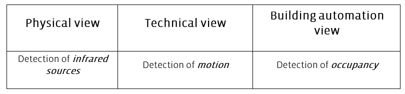
If the physical measurement method is the same, the different product names motion sensor and occupancy detector just shows different perspectives one the same product. Both names are used synonymously and can’t be distinguished.
Solely the technical characteristics of the product are responsible for the quality of motion or occupancy detection.
PIR motion sensors need a minimum of movement for a reliable function. If there is absolutely no movement the sensor can’t detect motion even if the name “occupancy detector” allows this fallacy.
Further information concernig this matter can be found at the whitepaper Motion and Occupancy detection in buildings.
Why does the motion sensor not detect movement?
Infrared motion sensors need a minimum of movement for a reliable function. Furthermore the motion sensor type, the detection range and the right placement are important.
The whitepaper Motion and occupancy detection in buildings deals with these points in detail.
BUS-Devices beter af met een DC of AC voeding?
NOVOS ruimteregelaars met Modbus- of BACnet-protocol kunnen zowel met wisselspanning (AC) als met gelijkspanning (DC) worden gevoed. Los daarvan genereert het interne spanningsbeheer een afgevlakte gelijkspanning voor de werking van elektronische componenten zoals het display, sensoren, enz.
Als meerdere apparaten tegelijkertijd worden ingeschakeld, tellen de afzonderlijke stromen op. Het spanningsverlies over de BUS-lijn mag er niet toe leiden dat een device onder de minimumspanning op de aansluitklem (15 V DC of 19 V AC) komt.
Voorbeeldcasus 1: 24 V AC of DC voeding + J-Y(St)Y 2x2xØ0.8 + 1x NOVOS Touch
Bij een lusweerstand van typ. 75 Ω/km van de vaak gebruikte BUS-kabel, J-Y(St)Y 2x2xØ0,8 en een voeding van 24 V DC, mag volgens de specs max. 24 V - 15 V = 9 V als spanningsverlies over de koperweerstand gerekend worden om vervolgens meer dan 15 V DC op de klemmen te garanderen.
Bij een wisselstroomvoeding mag er maximaal 5 V spanningsverlies zijn.
Gelijkspanning (DC) De berekende kabellengte L wordt berekend als: | Wisselspanning (AC) De berekende lijnlengte L wordt berekend als: |
Voorbeeldcasus 2: 24V AC of DC voeding + J-Y(St)Y 2x2xØ0.8 + 8x NOVOS Touch
Voor een buslijn met acht NOVOS Touch ruimte bedieningen bedraagt de toegestane berekende totale lengte van een AC-voeding slechts tussen 40 m en 70 m. De lengte is afhankelijk van de verdeling van de devices over de bus. De lengte hangt af van de verdeling van de devises over de BUS.
Bij een DC-voeding is een totale lengte tot 255 m mogelijk met een gelijkmatige verdeling.
Bij langere BUS-kabels moet de kabeldoorsnede van de draden voor de voeding groter worden gekozen (bijv. UNITRONIC® BUS PB FD P COMBI 1x2xØ0,64 + 3x1,0 mm² of UNITRONIC® BUS COMBI EIB 2x2xØ0,8+3x1,5 mm²). Daarnaast of als alternatief kan de busleiding aan beide uiteinden worden gevoed (ringleiding).
Als de spanningsval over de lijn te hoog wordt, zal dit leiden tot voortdurende pogingen om het toestel te starten. Het toestel begint de opstartprocedure (opstartscherm + pieptoon) en breekt het opstartproces na korte tijd af, omdat de spanning op de klemmen is gezakt.
Het toestel probeert opnieuw op te starten.
Met sensoren uit de USE-apparatenfamilie gebeurt in principe hetzelfde, maar het kan er anders uitzien door het ontbreken van een display en een zoemer.
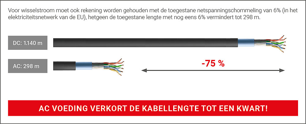
Conclusie:
De inkorting van de toegestane BUS-lengte is een hoge prijs voor de goedkopere wisselstroomvoeding. Daardoor blijft slechts ca. 25 % van de DC-kabellengte over bij AC!
Bovendien zijn de elektrische bedrijfskosten voor wisselstroom twee keer zo hoog als voor gelijkstroom (2,5 W tegen 5 VA). Het dubbel zo hoge vermogensverlies van de toestellen met wisselstroomvoeding leidt tot een dubbele zelfverwarming van de toestellen, die tijdens de
inbedrijfstelling moet worden gecompenseerd.
Bij AC-voeding bestaat ook het risico dat de RS485- transceivers worden vernietigd als de voedingsspanning niet in fase met alle eenheden wordt verbonden. Door de eenzijdige gelijkrichting is de wisselspanning niet meer polariteits-onafhankelijk! Dit probleem geldt voor regelaars en veldapparatuur.